

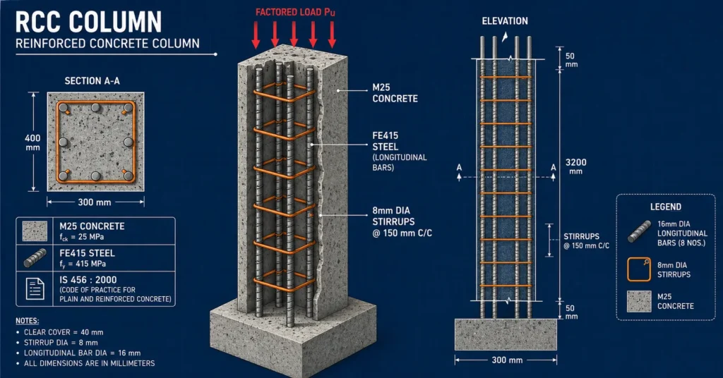
Column failure kills buildings. A 300 mm × 400 mm RC column looks solid, but size alone tells you nothing. What matters is whether it can carry the actual factored axial load from every floor, beam, and slab sitting on top of it.
Most engineers either guess (thumb rule) or run IS 456 formulas manually, one column at a time. That works, but it’s slow and error-prone. Our column load calculator gives you the factored capacity, safe load, bar count, and slenderness classification in real time, with a live cross-section that changes as you type.
This guide explains exactly how column load calculation works, what the IS 456 and ACI 318 formulas mean, and how to use the calculator correctly for both residential and multi-story buildings.
How to Use the Column Load Calculator
Select rectangular or circular shape, enter column dimensions (width, depth or diameter) and clear height in mm, then choose concrete and steel grades. Set your steel ratio (%) and bar diameter. The calculator instantly computes factored capacity (Pu), safe load, number of bars, slenderness ratio, and column type per IS 456 and ACI 318.
The calculator above is self-contained. Every input change triggers an instant recalculation and redraws the live column view. Here’s what each input controls:
- Shape: Rectangular or Circular For residential and commercial buildings, rectangular columns (b × d) are standard. Circular columns appear in bridge piers, elevated tanks, and architectural projects. The cross-section SVG updates immediately when you switch shapes.
- Dimensions (b, d, or D) in mm Enter width (b) and depth (d) for rectangular, or diameter (D) for circular. The aspect ratio of the cross-section drawing tracks your actual b/d ratio, so a 300 × 600 column looks twice as tall as it is wide.
- Column Height (L) in mm Clear height between floor slab and beam soffit. The elevation view scales proportionally, so a 6 m column looks visually taller than a 3 m one, matching the real slenderness ratio.
- Concrete Grade (f’c / fck) M25 (25 MPa) is the minimum recommended for columns per IS 456. Higher grades increase axial capacity substantially. M30 or M35 is typical for columns in 5+ story buildings.
- Steel Grade (fy) and Ratio (%) Fe415 is standard for most projects. Steel ratio between 1% and 4% covers most practical columns. IS 456 sets a minimum of 0.8% and a maximum of 8% of gross cross-sectional area.
- Applied Load Check Enter your factored applied load (kN). The load utilisation bar turns green below 85%, orange near the limit (85–100%), and red when the column is overstressed. This is a quick pass/fail check.
Run the calculator with your estimated tributary area load first. If utilisation exceeds 75%, increase column size or concrete grade before finalising layout. Retrofitting a column is 10–15× more expensive than upsizing during design.
How Do You Calculate Load on a Column?
Column load is the sum of all vertical forces transferred to the column: dead load from slabs and beams, live load from occupancy, wall load, and the column’s own self-weight. Multiply each by the load factor (1.5 for IS 456, 1.2D + 1.6L for ACI 318), then compare the factored load to the column’s factored axial capacity.
Step 1: Identify the Tributary Area
Every column supports a portion of the floor area around it. For a regular grid, the tributary area is roughly half the span in each direction multiplied together. A column at the intersection of 5 m and 6 m spans carries approximately 5/2 × 6/2 = 7.5 m² of floor area.
Step 2: Calculate Slab and Beam Dead Load
A 150 mm RC slab weighs 0.15 × 25 = 3.75 kN/m². Add finishes (1–2 kN/m²), partitions (1 kN/m²), and beam self-weight distributed across the tributary area. Total dead load (DL) for a typical residential floor runs 6–8 kN/m².
Step 3: Add Live Load
IS 875 Part 2 specifies live loads: 2 kN/m² for residential floors, 3 kN/m² for offices, 4 kN/m² for assembly areas. Multiply by tributary area to get live load per column.
Step 4: Factor the Loads
Per IS 456 Clause 18.2.3, the factored load Pu = 1.5 × (DL + LL). This is the load your column design formula must satisfy.
Example: DL = 40 kN, LL = 15 kN
Pu = 1.5 × (40 + 15) = 82.5 kN
Sum the factored load from every floor above to get total column load at the base. A 5-story building with 82.5 kN per floor adds up to 412.5 kN at the ground column, before wall loads and self-weight.
What Is the Formula for Column Load Capacity?
Per IS 456-2000 Clause 39.3, the axial load capacity of a short RC column is Pu = 0.4 × fck × Ac + 0.67 × fy × Asc. Here fck is concrete characteristic compressive strength (MPa), Ac is net concrete area (mm²), fy is steel yield strength (MPa), and Asc is steel cross-section area (mm²). Safe load = Pu ÷ 1.5.
IS 456-2000 Formula (India)
Where:
fck = Characteristic compressive strength of concrete (MPa)
Ac = Net concrete area = Ag − Asc (mm²)
fy = Yield strength of steel (MPa)
Asc = Total area of longitudinal steel (mm²)
Ag = Gross cross-sectional area (mm²)
ACI 318 Formula (USA / International)
Where:
φ = Strength reduction factor = 0.65 (tied), 0.75 (spiral)
f’c = Specified compressive strength (MPa)
Ast = Total steel area (mm²)
Why the Two Formulas Give Different Values
IS 456 uses 0.4 × fck as the concrete contribution, while ACI uses 0.85 × f’c with a φ factor applied. The net result: for M25 concrete and Fe415 steel, IS 456 typically gives a slightly more conservative safe load than ACI 318 for the same column. This difference rarely exceeds 5–8% for typical column proportions.
Always use IS 456 for projects under Indian codes and ACI 318 for US or internationally-contracted work. Mixing the two formulas in one project is a code violation and can create liability.
Short Column vs Slender Column: What’s the Difference?
A short column (slenderness ratio Le/D ≤ 12) fails by material crushing, and the IS 456 axial capacity formula applies directly. A slender column (12 < Le/D ≤ 60) can buckle before reaching full material capacity. Slender columns need moment magnification per IS 456 Clause 39.7 or Euler’s formula checks before calculating safe load.
Slenderness Ratio (Le/D)
Slenderness ratio = Effective length (Le) ÷ Least lateral dimension (D). Effective length depends on end conditions: Le = 0.5L (both ends fixed), 0.7L (one fixed, one pinned), 1.0L (both pinned), 2.0L (one fixed, one free).
The calculator uses Le = 0.7 × L as a conservative default for columns in framed structures, which suits most residential and commercial building columns.
| Column Type | Le/D Range | Failure Mode | Design Approach | IS 456 Reference |
|---|---|---|---|---|
| Short Column | ≤ 12 | Crushing (material failure) | Clause 39.3 formula direct | Cl. 25.1.2 |
| Slender Column | 12 to 30 | Combined crushing + buckling | Moment magnification required | Cl. 39.7 |
| Long Slender | 30 to 60 | Buckling dominant | Second-order analysis needed | Cl. 39.7 |
| Max Permitted | 60 (hard limit) | Unstable | Not permitted beyond this | Cl. 25.3.1 |
Euler’s Buckling Formula for Slender Columns
For steel columns or very slender RC members, Euler’s formula gives the critical buckling load:
Where:
E = Modulus of elasticity (N/mm²)
I = Moment of inertia of cross-section (mm⁴)
Le = Effective length (mm)
For RC columns, E = 5000 × √fck (MPa) per IS 456. A column with Le/D above 40 should always get an explicit Euler check, especially for steel columns where E = 200,000 MPa and buckling risk is significant.
How to Calculate Column Self-Weight
Column self-weight (kN) = Cross-section area (m²) × Height (m) × 25 kN/m³. For a 300 mm × 400 mm column, 3 m tall: 0.3 × 0.4 × 3 × 25 = 9 kN per floor. This amount is added to beam and slab loads at each storey level when calculating cumulative column load at the base.
Per-Floor Self-Weight Calculation
Unit weight of reinforced concrete is standardised at 25 kN/m³ per IS 875 Part 1. The formula is clean:
W_col = (π/4 × D²) × H × 25 (circular)
Note: b, d, D in metres; H = clear height in metres
Example: 5-Story Building Column
Say you have a 400 mm × 500 mm column, 3.5 m clear height per floor, over 5 stories:
Self-weight per floor = 0.4 × 0.5 × 3.5 × 25 = 17.5 kN
Total self-weight (5 floors) = 17.5 × 5 = 87.5 kN
That’s not negligible. For heavy columns in tall buildings, self-weight can contribute 10–15% of total axial load. Always include it in your base column design.
Total Column Load for Multi-Story Buildings
Total column load at base = (Dead load + Live load) × tributary area × number of floors + total wall load + cumulative column self-weight. Apply a load factor of 1.5 per IS 456 to get the factored axial load (Pu). For a quick estimate, use 10–12 kN/m² per floor for residential buildings and multiply by tributary area × floors.
Step-by-Step Multi-Story Load Calculation
Here’s how Ahmed, a structural engineer in Karachi, calculated the base column load for a 4-story residential building with 5 m × 5 m column grid:
| Load Type | Value per m² | Area or Factor | Per Floor (kN) | Total 4 Floors (kN) |
|---|---|---|---|---|
| Slab dead load | 3.75 kN/m² | 6.25 m² (trib.) | 23.4 | 93.8 |
| Finishes + partitions | 2.0 kN/m² | 6.25 m² | 12.5 | 50.0 |
| Beam self-weight | — | Estimated | 8.0 | 32.0 |
| Live load (residential) | 2.0 kN/m² | 6.25 m² | 12.5 | 50.0 |
| Wall load (230 mm brick) | 4.7 kN/m | 4 m height × perimeter share | 18.8 | 75.2 |
| Column self-weight | — | 0.3×0.4×3.0×25 | 9.0 | 36.0 |
| Total Service Load | — | — | 84.2 | 337.0 kN |
| Factored Load (×1.5) | — | IS 456 | — | 505.5 kN |
Using the calculator with M25 concrete, Fe415 steel, 300 mm × 400 mm, 2% steel ratio: safe load = 580 kN. The 505.5 kN factored load gives a utilisation of 87%. Ahmed upsized to 350 × 450 mm, dropping utilisation to 70% and giving comfortable headroom.
Tributary Area for Irregular Grids
For non-square grids, tributary area = (span1/2) × (span2/2) for an interior column. Corner columns carry 1/4 of the adjacent bays, edge columns carry 1/2. In irregular layouts, use the actual load path from beam reactions, not a simplified tributary area.
For a rough initial column size in a residential building, use this thumb rule: Ag (mm²) = Total factored axial load (N) ÷ (0.4 × fck). With M25 concrete: Ag ≈ Pu ÷ 10. Then verify with the full IS 456 formula and adjust for steel ratio.
How to Determine Minimum Column Size for a Building
Minimum column size per IS 456 is 200 mm in any direction for rectangular columns. For practical design, start with Ag = Pu ÷ (0.4 × fck) assuming 2–3% steel, then check slenderness ratio. Most 2-story residential buildings work with 230 × 230 mm or 230 × 300 mm columns using M20–M25 concrete.
| Stories | Axial Load Range (kN) | Min Column Size | Recommended Size | Steel Ratio |
|---|---|---|---|---|
| G+1 (2-story) | 150–350 kN | 200 × 200 mm | 230 × 300 mm | 1.0–1.5% |
| G+2 (3-story) | 350–600 kN | 230 × 300 mm | 300 × 400 mm | 1.5–2.0% |
| G+3 (4-story) | 600–900 kN | 300 × 400 mm | 350 × 450 mm | 2.0–2.5% |
| G+4 (5-story) | 900–1300 kN | 350 × 450 mm | 400 × 500 mm | 2.0–3.0% |
| G+7 (8-story) | 1300–2200 kN | 450 × 550 mm | 500 × 600 mm | 2.5–4.0% |
| G+10 (11-story) | 2200–3500 kN | 550 × 650 mm | 600 × 750 mm | 3.0–5.0% |
RC column minimum sizing guide per IS 456 for residential buildings G+1 to G+10 — M25 concrete, Fe415 steel, 2% steel ratio
Slenderness Check for Column Sizing
Once you’ve sized for axial load, verify slenderness ratio. A 230 × 230 mm column in a 3 m storey height: Le = 0.7 × 3000 = 2100 mm, Le/D = 2100 ÷ 230 = 9.1. That’s comfortably a short column (below 12). If your site has high floor-to-floor heights (4+ m), check slenderness early in sizing.
| Column Size | Gross Area (mm²) | Pu (kN) | Safe Load (kN) | Bars (16mm Ø) |
|---|---|---|---|---|
| 200 × 200 | 40,000 | 467 | 311 | 4 |
| 230 × 230 | 52,900 | 618 | 412 | 4 |
| 300 × 300 | 90,000 | 1,051 | 701 | 6 |
| 300 × 400 | 120,000 | 1,401 | 934 | 6 |
| 350 × 450 | 157,500 | 1,839 | 1,226 | 8 |
| 400 × 500 | 200,000 | 2,335 | 1,556 | 8 |
| 450 × 600 | 270,000 | 3,152 | 2,101 | 10 |
| 500 × 700 | 350,000 | 4,086 | 2,724 | 12 |
| Ø 400 (circular) | 125,664 | 1,467 | 978 | 8 |
| Ø 500 (circular) | 196,350 | 2,293 | 1,528 | 10 |
Frequently Asked Questions About Column Load Calculation
How do you calculate load on a column?
Column load is the sum of all vertical forces transferred to that column: dead load from slabs and beams (calculated from tributary area), live load from occupancy per IS 875, wall loads, and column self-weight (b × d × H × 25 kN/m³). Apply load factor 1.5 per IS 456 to get factored load Pu. Then compare Pu against the column’s axial capacity from the IS 456 formula.
What is the formula for column load capacity?
Per IS 456-2000 Clause 39.3: Pu = 0.4 × fck × Ac + 0.67 × fy × Asc, where fck = concrete grade (MPa), Ac = concrete area (mm²), fy = steel yield strength (MPa), and Asc = steel area (mm²). Safe load = Pu ÷ 1.5. For ACI 318: Pu = 0.65 × [0.85 × f’c × (Ag − Ast) + fy × Ast].
What is the minimum size of a column?
IS 456-2000 specifies a minimum dimension of 200 mm for any side of a rectangular RC column. In practice, 230 × 230 mm is the smallest column used in residential buildings. For high-seismic zones, IS 13920 recommends a minimum of 300 mm in the direction of earthquake loading.
What is the difference between short column and slender column?
A short column has slenderness ratio Le/D ≤ 12 and fails by crushing. A slender column has Le/D between 12 and 60 and is prone to buckling before reaching full compressive capacity. Per IS 456, slender columns need additional moment magnification using the method in Clause 39.7 before computing safe load.
How to calculate column self-weight?
Column self-weight = cross-section area (m²) × height (m) × 25 kN/m³. A 300 × 400 mm column, 3 m tall: 0.3 × 0.4 × 3 × 25 = 9 kN. For a 5-story building, that’s 45 kN cumulative at the base column. Always add this to beam and slab loads when calculating total axial load.
What is the thumb rule for column design?
Thumb rule: Ag (mm²) = Total factored load (N) ÷ (0.4 × fck). With M25 concrete, Ag ≈ Pu (in N) ÷ 10. For a 500 kN factored load: Ag = 500,000 ÷ 10 = 50,000 mm² = 224 × 224 mm minimum. Round up to 230 × 230 mm, verify with IS 456 formula, then check slenderness ratio.
How to calculate total load on column for multi-story building?
Total base column load = sum of [(Dead load + Live load) × tributary area + wall load + column self-weight] for each floor. Apply load factor 1.5. Quick estimate: 10–12 kN/m² per floor × tributary area × number of floors. A 6.25 m² column in a 5-story building carries roughly 10 × 6.25 × 5 = 312.5 kN service load, or 469 kN factored.
What is the slenderness ratio limit for RC columns per IS 456?
IS 456 Clause 25.3.1 sets the maximum slenderness ratio (Le/D) at 60 for RC columns. Columns with Le/D ≤ 12 are short columns. Those with Le/D from 12 to 60 are slender and require moment magnification analysis. Exceeding 60 is not permitted under IS 456 for conventionally designed columns.
Conclusion
Getting column load calculation right isn’t optional. Every floor you add concentrates more load at the base column, and a 10% underestimate on a 6-story building can mean a 600 kN error. That’s a column failure waiting to happen.
The column load calculator on this page handles IS 456 and ACI 318 axial capacity, live slenderness ratio checks, bar counts, and load utilisation in real time. Use it to verify sizes quickly, then hand off the confirmed geometry and steel layout to your structural drawings.
For more civil engineering calculators, explore our full calculator suite. And if you’re sizing footings below these columns, our isolated footing calculator picks up exactly where this one leaves off.
Sources & Further Reading
Last Updated: | Next Review:
- Bureau of Indian Standards. “IS 456:2000 — Plain and Reinforced Concrete Code of Practice (4th Revision).” BIS, 2000.
- American Concrete Institute. “ACI 318-19: Building Code Requirements for Structural Concrete.” ACI, 2019.
- Bureau of Indian Standards. “IS 875 Part 2:1987 — Code of Practice for Design Loads (Imposed Loads).” BIS, 1987.
- Bureau of Indian Standards. “IS 13920:2016 — Ductile Design and Detailing of RC Structures.” BIS, 2016.