

Free Beam Load Calculator — Steel & Wood Design with AISC and NDS
Most beams don’t fail because the stress is too high. They fail because they deflect too much — floors bounce, ceilings crack, clients complain. According to AISC’s Steel Construction Manual, deflection governs the final member selection in the majority of floor beam designs, yet most free online tools only give you a shear diagram and call it done.
If you’ve ever plugged numbers into a free beam calculator and gotten back a pretty diagram but zero actual design checks, you know the problem. No pass/fail. No LRFD combinations. No LTB check. Certainly no NDS wood design. You still have to do all the real work yourself.
This page embeds a fully working beam load calculator that runs AISC 360 bending and shear checks, lateral-torsional buckling per §F2, ASCE 7-22 load combinations (D, L, Lr, S, W), and NDS wood design — all free, no login needed. Below the tool, you’ll find plain-English explanations of what every output actually means.
What Is a Beam Load Calculator?
A beam load calculator is a structural analysis tool that computes support reactions, shear forces, bending moments, and deflections for a loaded beam. Advanced versions also run design code checks — verifying whether a selected steel or wood section passes AISC, NDS, or Eurocode requirements for the applied loads.
Think of a beam like a shelf bolted between two walls. Put weight on it and four things happen: the supports push back (reactions), the internal material resists being cut (shear), the beam tries to curve (bending moment), and the whole thing sags (deflection). A beam load calculator quantifies all four — instantly, without setting up a spreadsheet.
What a Complete Calculator Covers
| Output | What It Tells You | Used For |
|---|---|---|
| Support Reactions | Vertical forces at each bearing point | Column and footing design |
| Shear Force Diagram | Internal horizontal slice forces along beam | Web crippling, connection design |
| Bending Moment Diagram | Internal rotation forces — peak = critical section | Section size selection |
| Deflection | Physical sag at any point along span | Serviceability checks (L/360, L/240) |
| D/C Ratio | Demand ÷ Capacity — should be ≤ 1.0 | Pass/fail design check |
| LTB Check | Reduced moment capacity due to unbraced length | AISC 360 §F2 compliance |
Who Uses Beam Calculators?
Structural engineers use them to confirm preliminary hand calculations before running full models. Contractors use them to verify supplier load tables before ordering steel. Students use them to check homework. If you’re sizing a floor beam, a header over a garage door, or a ridge beam for a residential addition — this is your tool.
Pro Tip: Always run the calculator twice — once with service loads (D+L) to check deflection, and once with factored loads (LRFD combos) to check bending strength. The governing case is often different. Our calculator does both automatically.
How to Use the Beam Load Calculator — Step by Step
Set your beam type and span, enter load cases by category (D, L, Lr, S, W), pick your section and material, then read the D/C ratios and deflection results. The calculator handles all ASCE 7 load combinations automatically — you just need your unfactored loads.
- Choose Beam Type and Span
Select from simply supported, fixed-fixed, fixed-pinned, cantilever, or 2–3 span continuous. Enter the total span in feet or meters. For continuous beams, individual span lengths appear automatically.
- Enter Load Cases by Category
Go to the Loads tab. You’ll see five rows: D (Dead), L (Live), Lr (Roof Live), S (Snow), W (Wind). Enter unfactored UDL in k/ft and any point loads with their positions. The calculator applies ASCE 7-22 combinations automatically.
- Pick Your Section and Material
Choose a W-shape, S-shape, HSS, or Pipe from the database. For wood design, switch the design code to NDS and select species, size, and moisture condition. Or enter custom section properties directly.
- Check LTB Inputs (Steel Only)
Go to the LTB tab. Enter your unbraced length Lb. If you leave it blank, the full span is used (conservative). The Cb factor defaults to 1.0 — enter actual values for partial bracing.
- Read the Results
The five metric cards at the top show peak values at a glance. Scroll down for shear and moment diagrams, deflection check, bending/shear D/C ratios, and the full LTB analysis. Green badge = pass, red = increase the section.
Pro Tip: Use the “Find Lightest Passing Section” button in the Analysis tab. It scans all 46 W-shapes in the database and returns the 5 lightest sections that pass bending, LTB, shear, and deflection checks simultaneously. Faster than manual trial-and-error.
ASCE 7 Load Combinations — What They Mean and Why They Matter
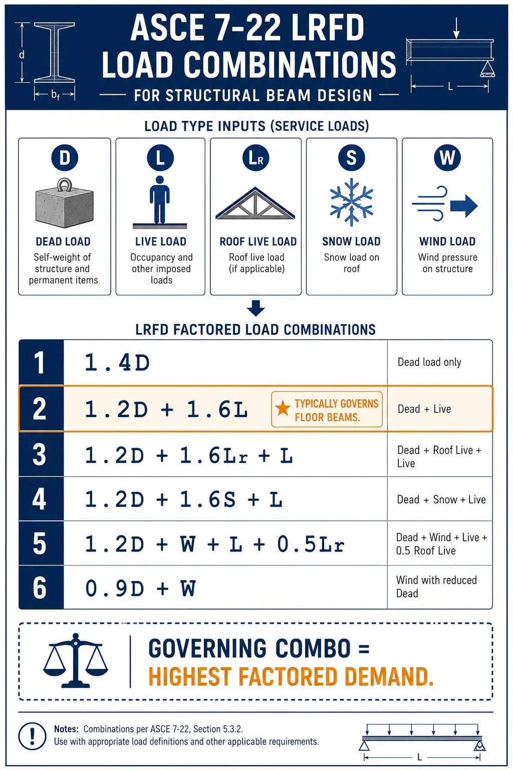
ASCE 7-22 load combinations apply safety factors to different load types before checking structural capacity. For LRFD, the critical combo is typically 1.2D + 1.6L for floor beams — meaning dead loads are factored 1.2× and live loads 1.6× before comparing against the beam’s design strength.
Engineers don’t design beams for the loads that are actually there. They design for the loads multiplied by safety factors — because real loads vary, materials have variability, and you don’t want a floor to fail if a party is a bit heavier than planned.
The Five Load Types, Simply Explained
| Category | Code | What’s Included | Typical Range (psf) |
|---|---|---|---|
| Dead Load | D | Structure self-weight, floor finishes, permanent fixtures | 10–30 psf |
| Live Load | L | People, furniture, moveable equipment | 40–100 psf |
| Roof Live Load | Lr | Construction workers, equipment on roof | 12–20 psf |
| Snow Load | S | Ground snow × exposure, thermal, importance factors | 0–60 psf |
| Wind Load | W | Horizontal and uplift pressure from wind | Project-specific |
LRFD vs. ASD — Which Should You Use?
LRFD (Load and Resistance Factor Design) is the modern method — used by most structural engineers since the 1990s. It applies load factors to demands and resistance factors (φ) to capacities. ASD (Allowable Stress Design) is older but still used for some wood and connection design. Both are valid per AISC 360-22. When in doubt, use LRFD.
Lateral-Torsional Buckling — What It Is and Why It Matters
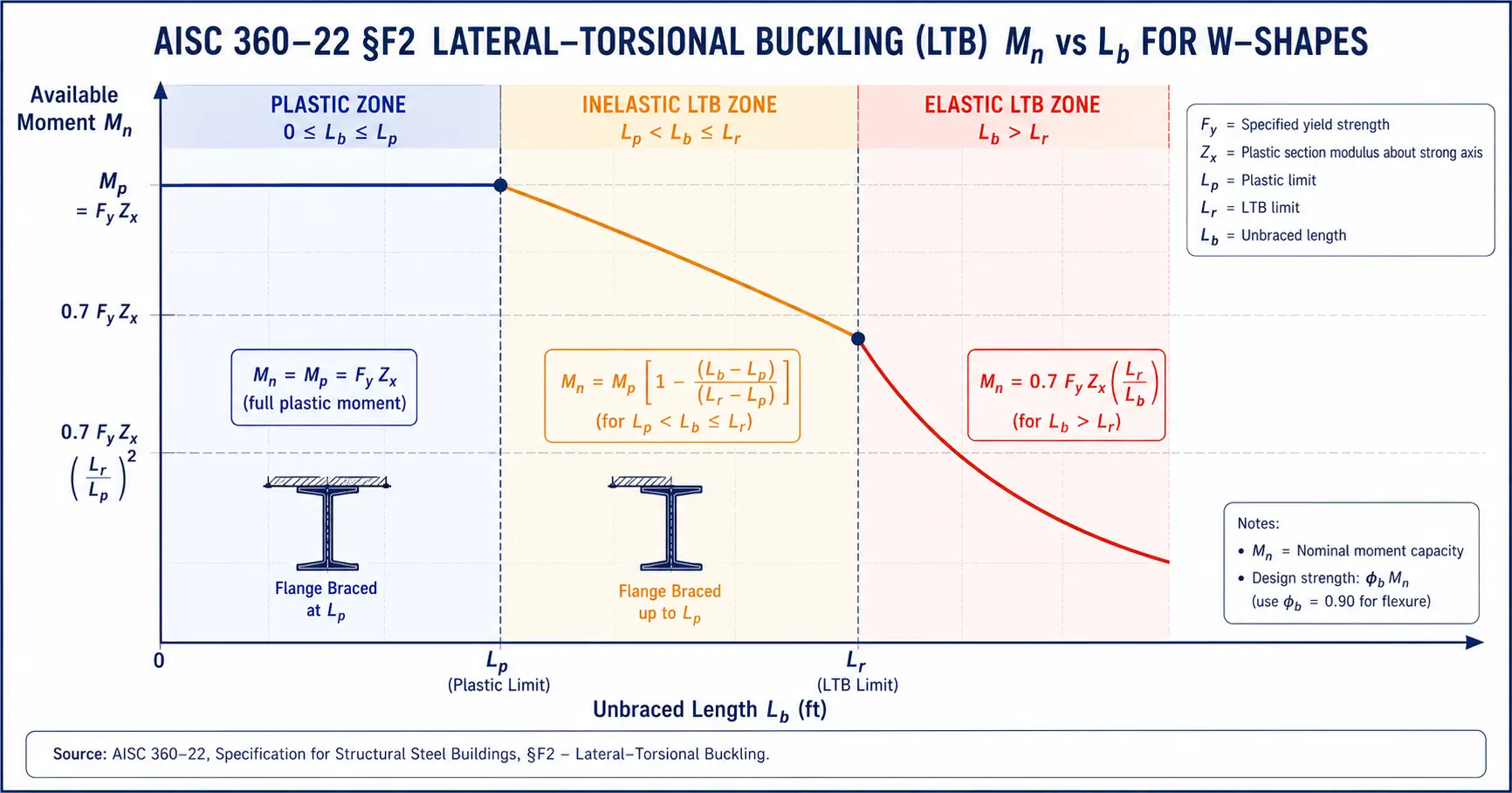
Lateral-torsional buckling (LTB) occurs when a beam’s compression flange buckles sideways before the steel yields. It reduces available moment capacity below the plastic moment. AISC 360-22 §F2 divides behavior into three zones based on unbraced length: plastic (full capacity), inelastic LTB (partial), and elastic LTB (significantly reduced).
Hold a 12-inch ruler flat and press down on the middle. It bends predictably. Now hold it on edge — like an I-beam — and press down. At some point it rolls sideways instead of bending straight down. That’s LTB.
For steel I-beams, the compression flange wants to buckle laterally when it’s not braced. How far the beam can go before this happens depends on the unbraced length (Lb) — the distance between points where the compression flange is restrained.
The Three LTB Zones per AISC 360-22 §F2
| Zone | Condition | Available Moment Mn | What It Means |
|---|---|---|---|
| Plastic | Lb ≤ Lp | Full plastic moment Mp = FyZx | Bracing is close enough — full capacity |
| Inelastic LTB | Lp < Lb ≤ Lr | Linear reduction from Mp to 0.7FySx | Partial capacity — brace more for efficiency |
| Elastic LTB | Lb > Lr | Fcr × Sx (can be much less than Mp) | Significant capacity loss — add bracing |
When LTB Actually Governs
For most floor beams with decking attached, the compression flange is continuously braced — LTB doesn’t govern. For roof beams without decking, long spans with widely spaced purlins, or any beam with Lb greater than about 10–15 feet, LTB can reduce capacity by 20–50%. Always check it.
When LTB Doesn’t Apply
HSS rectangular and square sections, pipes, and wood members don’t experience LTB the same way — their closed shapes resist lateral buckling naturally. The calculator automatically marks LTB as “N/A” for those section types.
Steel vs. Wood Beam Design — Key Differences
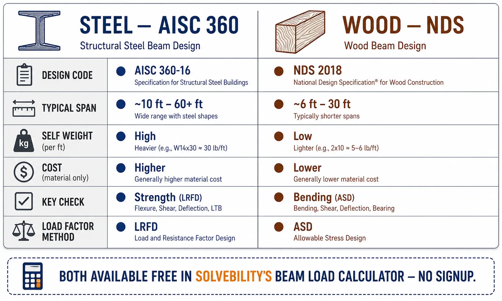
Steel and wood beams solve the same problem but play by different rules. Steel uses AISC 360, wood uses NDS (National Design Specification). Both are available in this calculator — just switch the design code in the Beam tab.
When Steel W-Shapes Win
Long spans (20+ feet), heavy loads, and tight depth constraints are where steel earns its cost premium. A W18×55 can span 30 feet carrying 1 kip/ft with a 1.5-inch deflection limit. Matching that in wood would take a 6×16 triple-ply glulam.
When Wood Works Better
Residential floor and roof framing, 8–20 foot spans, wood-framed walls — NDS-designed sawn lumber or engineered lumber (LVL, PSL) is usually cheaper and faster to install than steel. The NDS approach uses allowable stress design with duration-of-load factors (CD) that actually increase capacity for short-term loads like snow.
Section Optimizer — Finding the Lightest Beam
The optimizer in the Analysis tab scans 46 W-shapes, runs every LRFD combo and the LTB check for each, and ranks passing sections by weight. The lightest passing section isn’t always the cheapest — availability matters — but it’s the right starting point for procurement.
What Do the Results Actually Mean?
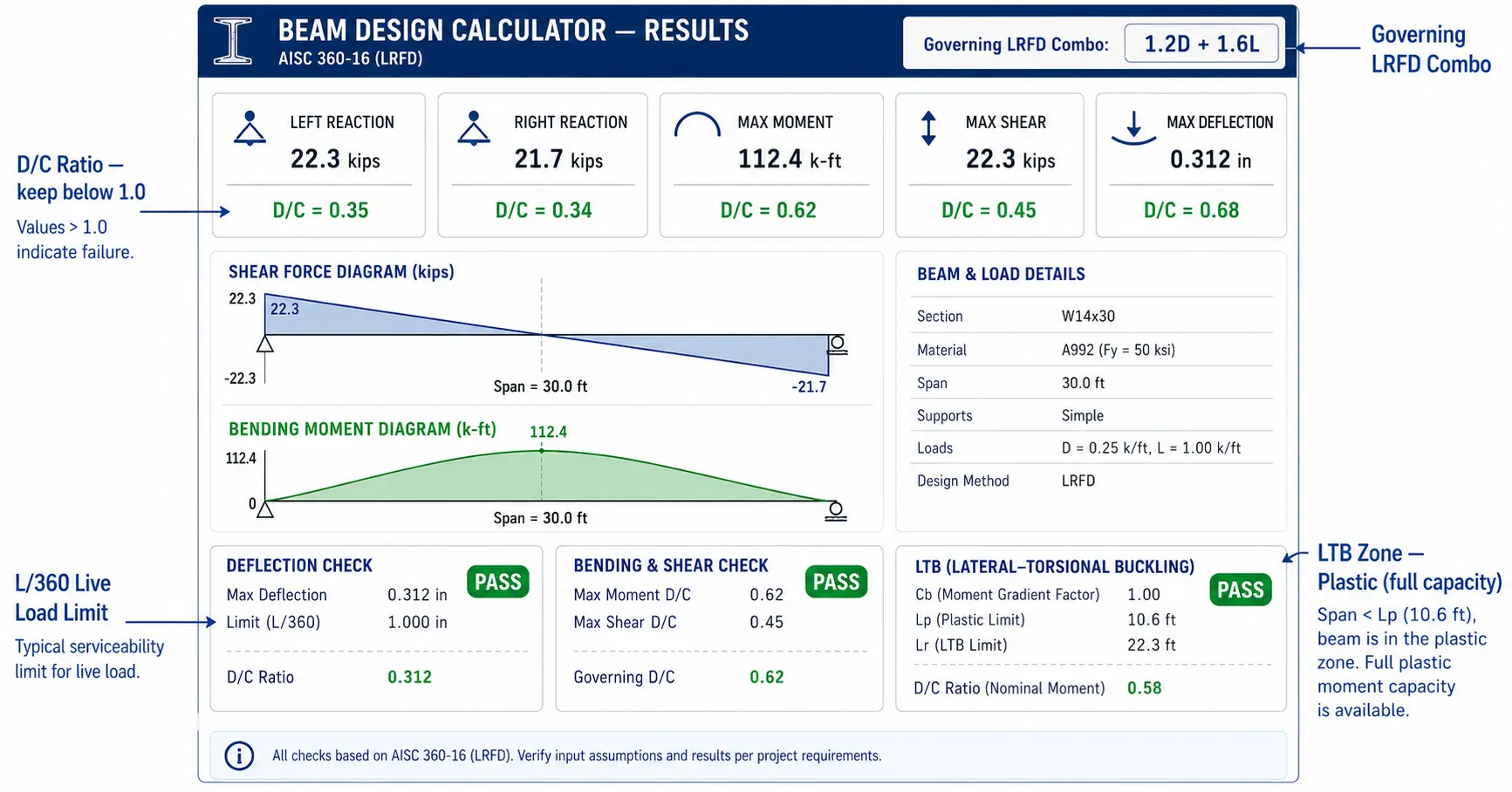
The D/C ratio (Demand ÷ Capacity) is the key number — keep it below 1.0. Bending D/C below 1.0 means the section is strong enough. Deflection is checked separately against serviceability limits: L/360 for live load, L/240 for total load. Both must pass for the beam to be acceptable.
Reading D/C Ratios
A D/C ratio of 0.85 means the beam is using 85% of its capacity — good. A ratio of 1.12 means you’re 12% over capacity — pick the next size up. Aim for 0.80–0.95 in practice: efficient without being under-designed.
Deflection Limits — L/360 vs. L/240
L/360 (span ÷ 360) is the standard live-load limit for floors supporting plaster or tile — a 20-foot beam can deflect no more than 0.67 inches under live load alone. L/240 is used for total load (dead + live) or for roof members. The calculator checks both automatically and flags whichever governs.
What to Do When Something Fails
If bending fails, increase the section depth — Z grows with d³. If deflection fails, increase the moment of inertia — a deeper section or switching from S to W-shape usually fixes it. If LTB fails, add a brace point at midspan — this cuts Lb in half and typically pushes the section into the plastic zone.
Free Beam Load Calculators — Honest Comparison
There are good free beam tools out there. Here’s what each actually gives you for zero cost — no marketing, just features.
| Tool | AISC Design Checks | LTB Check | ASCE 7 Combos | NDS Wood | Continuous Spans | No Login |
|---|---|---|---|---|---|---|
| Solvebility (this page) | ✓ Full LRFD/ASD | ✓ §F2 | ✓ 6 combos | ✓ NDS | ✓ Up to 3 | ✓ |
| WebStructural | ✓ LRFD/ASD | ✓ | ✓ | ✓ | ✓ | ✓ |
| SkyCiv Free | ✗ Analysis only | ✗ | ✗ | ✗ | ✓ | ✓ |
| ASDIP Free | ✓ (limited) | ✗ (paid) | ✓ | ✗ | ✓ 3 spans | ✓ |
| Omnicalculator | ✗ | ✗ | ✗ | ✗ | ✗ Simply supported only | ✓ |
| StructureCalcs | ✗ Analysis only | ✗ | ✗ | ✗ | ✓ Unlimited | ✓ |
SkyCiv and StructureCalcs are excellent for structural analysis — shear, moment, deflection diagrams are clean and accurate. But design code checks cost money on both platforms. If you need actual pass/fail answers for AISC 360 or NDS, Solvebility and WebStructural are the two genuinely free options with full design functionality.
Frequently Asked Questions
A beam load calculator is a structural engineering tool that computes reactions, shear forces, bending moments, and deflections for a beam under applied loads. Advanced versions — like this one — also run design code checks per AISC 360 or NDS, telling you whether a specific section passes or fails for your load case. It replaces hours of manual calculation with instant, verified results.
Beam load capacity depends on section modulus (S or Z), material yield strength (Fy), and the design method (LRFD or ASD). For LRFD steel: ϕMn = 0.9 × Fy × Zx. For ASD: Fb = 0.66 × Fy. You then compare factored demand (Mu) against design capacity (ϕMn) — the D/C ratio must stay at or below 1.0. Enter your section and loads into the calculator above and it handles all of this automatically.
LRFD (Load and Resistance Factor Design) applies load factors to demands and resistance factors to capacities — checking that factored demand ≤ φ × nominal capacity. ASD (Allowable Stress Design) divides nominal capacity by a safety factor (Ω) and checks that actual stress stays below the allowable. LRFD is the current standard per AISC 360-22 and generally produces more efficient designs for steel. Both methods are available in this calculator.
Yes — the LTB check follows AISC 360-22 §F2 and runs automatically for all W-shape, S-shape, and custom I-beam sections. Enter your unbraced length (Lb) and Cb factor in the LTB tab. The calculator classifies your beam into the plastic, inelastic LTB, or elastic LTB zone, computes the reduced moment capacity (ϕMn), and compares it against the governing factored moment (Mu). HSS, pipe, and wood sections are marked N/A since they don’t govern by LTB.
Yes. Switch the design code to NDS in the Beam tab. Select your species (Douglas Fir-Larch, Southern Pine, Hem-Fir, or SPF), nominal size (2×8 through 8×12), and moisture condition. The calculator applies the NDS adjustment factors — size factor (CF), wet service factor (CM), and load duration factor (CD per combo) — and checks adjusted bending stress (Fb′) and shear (Fv′) against actual demands.
For floor beams supporting brittle finishes (tile, plaster), use L/360 for live load and L/240 for total load (dead + live). For roof members without brittle finishes, L/240 for live and L/180 for total is typical. IBC Table 1604.3 provides the full reference. In this calculator, set your limits in the LTB/Analysis tab — both live and total deflection are checked and reported separately.
Start Designing Beams the Right Way
A beam load calculator that only draws diagrams isn’t a design tool. It’s a preview. Real design means checking bending strength against factored loads, verifying LTB for the actual unbraced length, confirming deflection stays inside L/360 for live load, and doing all of it for every applicable ASCE 7 load combination simultaneously.
That’s what this beam load calculator does — free, in your browser, no account required. Whether you’re sizing a steel W-shape for a 30-foot floor beam or checking a triple-ply 2×12 Douglas Fir header over a garage opening, the workflow is the same: enter your loads by category, pick your section, and read the pass/fail.
For more structural tools, explore Solvebility’s civil engineering calculators — including the excavation volume calculator and concrete mix design calculator.
Run Your Beam Design Now
Free. No login. AISC 360 + NDS + ASCE 7 load combinations — all in one tool.
↑ Use the Calculator AboveReferences
- American Institute of Steel Construction (AISC). Specification for Structural Steel Buildings, AISC 360-22. Chicago: AISC, 2022. aisc.org
- American Society of Civil Engineers. Minimum Design Loads and Associated Criteria for Buildings and Other Structures, ASCE 7-22. Reston: ASCE, 2022. asce.org
- American Wood Council. National Design Specification (NDS) for Wood Construction, 2024 Edition. Leesburg: AWC, 2024. awc.org
- American Institute of Steel Construction. Steel Construction Manual, 16th Edition. Chicago: AISC, 2023.
- International Code Council. International Building Code, IBC 2024, Table 1604.3 — Deflection Limits. Country Club Hills: ICC, 2024. iccsafe.org
Last Updated: June 2026 | Next Review: December 2026 | Reviewed against AISC 360-22, ASCE 7-22, NDS 2024
Written by Nouman Ahmed
Civil Engineer • Solar Energy Consultant • Software Developer
Nouman is the founder of Solvebility, with practical experience in solar PV system design, engineering calculations, and calculator development since 2011. This tool was built by Nouman and reviewed by the Solvebility engineering team to verify formulas, assumptions, and calculation accuracy before publication — and is updated whenever industry standards change.