

Last Updated: June 2026 | Next Review: December 2026 | Reviewed by a licensed civil engineer
Structural Load Calculator: Free ASCE 7-22 Tool for Engineers
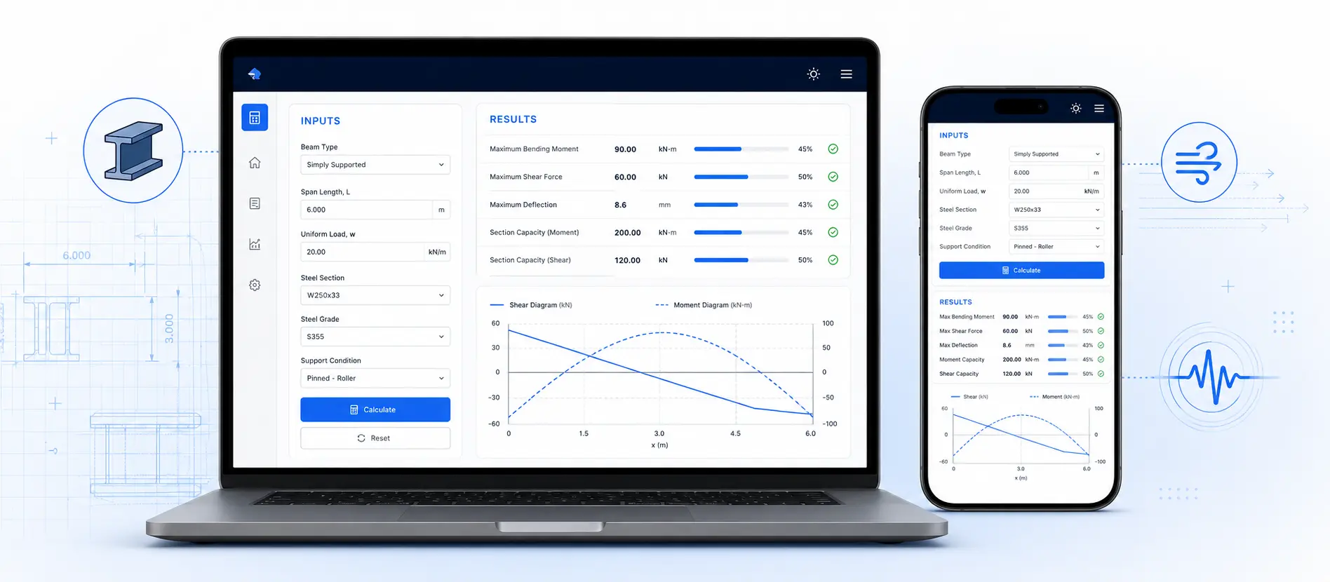
Solvebility’s free structural load calculator covers 6 engineering modules — from load combinations to seismic base shear — all in one browser tab.
A structural engineer once told me: “I’ve verified the same LRFD combo on 3 different spreadsheets before sending it to the client.” That’s not caution — that’s a broken workflow. If you’re calculating structural loads by hand or juggling disconnected tools, you’re spending time you don’t have on math that a free browser tool can handle in seconds.
Most free tools online do one thing: dead load or wind pressure or beam deflection — never all of them together. That means you’re tabbing between tools, copying numbers, and hoping nothing breaks in the handoff.
This guide walks through exactly how a proper structural load calculator should work, what ASCE 7-22 actually requires at each step, and how Solvebility’s free tool handles all 6 modules — load combinations, beam analysis, tributary area, wind, seismic, and printed reports — in a single page. All calculations are based on ASCE 7-22, ACI 318, and standard structural mechanics.
What Is a Structural Load Calculator?
A structural load calculator is a tool that takes service-level loads (dead, live, wind, snow, seismic) and evaluates the factored load combinations required by ASCE 7-22 to find the governing design demand. It outputs the maximum force a structural member — beam, column, or foundation — must safely resist, along with shear, moment, deflection, and lateral loads.
Think of it as a code-checking machine. You feed it real numbers from your project — floor loads in psf, wind speed in mph, site class, building height — and it applies every ASCE 7-22 load combination simultaneously, flags the worst case, and shows you exactly why it governs.
A proper structural load calculator isn’t just an equation wrapper. It handles:
- Load types: dead (D), live (L), roof live (Lr), snow (S), rain (R), wind (W), seismic (E)
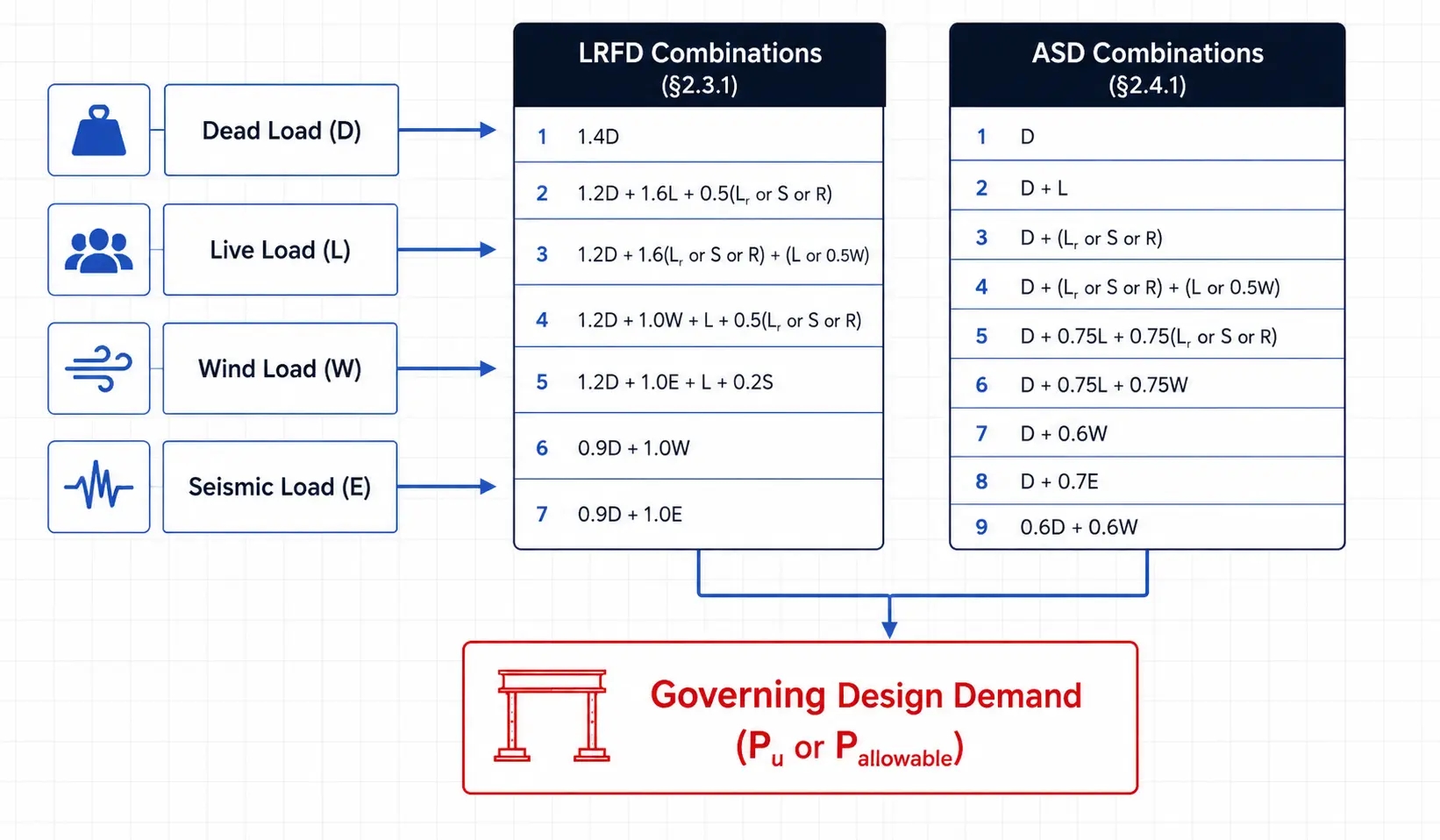
- LRFD strength combinations per ASCE 7-22 §2.3.1 (7 combinations)
- ASD allowable stress combinations per ASCE 7-22 §2.4.1 (9 combinations)
- Beam analysis: reactions, shear, moment, deflection for simply supported, cantilever, and fixed-fixed spans
- Tributary area: interior, edge, and corner column load accumulation
- Wind pressure: velocity pressure, MWFRS directional procedure, base shear
- Seismic: response coefficient Cs, period T, and base shear V per §12.8
Mark, a structural EIT from Houston I spoke with, described his old workflow: open one spreadsheet for LRFD combos, open another for beam deflection, open SkyCiv for wind speed, cross-reference everything by hand. He switched to a unified browser tool and cut his preliminary load check time from 45 minutes to 8.
For preliminary design, run all load combinations first. The governing combo tells you which load type controls — and that determines which analysis module you spend the most time in. Don’t start with beam sizing before you know whether wind or gravity governs.
How Do ASCE 7-22 Load Combinations Work?
ASCE 7-22 load combinations apply safety factor multipliers to service loads to get design demand. LRFD (strength) uses 7 combinations with factors like 1.2D + 1.6L. ASD uses 9 combinations without strength factors. The governing combination — the one producing the highest demand — controls member design. Engineers evaluate all combinations simultaneously, not one at a time.
The standard gives you 7 LRFD combos and 9 ASD combos. On a typical office building with dead, live, and wind, at least 4 of those combinations actively compete. The calculator evaluates all of them at once and highlights the winner in red.
The 7 LRFD Strength Combinations (ASCE 7-22 §2.3.1)
| # | Combination | Typical Governing Case |
|---|---|---|
| LC1 | 1.4D | Self-weight only, no live or lateral loads |
| LC2 | 1.2D + 1.6L + 0.5(Lr or S or R) | Most gravity-loaded floors — usually governs |
| LC3 | 1.2D + 1.6(Lr or S or R) + (L or 0.5W) | Roof with heavy snow and occupancy |
| LC4 | 1.2D + 1.0W + L + 0.5(Lr or S or R) | Windward walls, intermediate floors |
| LC5 | 0.9D + 1.0W | Overturning, uplift on leeward columns |
| LC6 | 1.2D + 1.0E + L + 0.2S | Seismic-controlled structures |
| LC7 | 0.9D + 1.0E | Net tension in seismic uplift conditions |
LC2 governs most office and residential floors. LC5 is the one that trips up newer engineers — the 0.9D reduction accounts for minimum dead load resisting overturning, which can make leeward column loads look surprisingly low.
LRFD vs. ASD: The Governing Ratio
The ratio between LRFD and ASD governing demands runs between 1.4 and 1.6 for most gravity-only cases. When wind or seismic dominates, that ratio shifts. The calculator shows you both governing values and their ratio so you can verify you’re comparing apples to apples across design methods.
If your LRFD/ASD ratio is outside the 1.4–1.6 range, double-check your lateral load inputs. An unusually low ratio often means seismic or wind is controlling a combination — and that’s worth knowing before you start sizing members.
Beam Analysis: Moment, Shear, and Deflection
Beam analysis calculates reactions, max bending moment (Mmax), max shear (Vmax), and maximum deflection (Δmax) for a given span, boundary condition, and load type. For a simply supported beam with a uniform distributed load w over span L: Mmax = wL²/8, Vmax = wL/2, and Δmax = 5wL⁴/384EI. Boundary conditions and load position change these formulas significantly.
Three boundary conditions cover most real-world cases:
Simply Supported Beam
Both ends are free to rotate. This is the most common condition — a steel beam spanning between columns with standard bolted connections. For a uniform load w (kip/ft) over span L (ft):
- Reactions: RL = RR = wL/2
- Max moment at midspan: Mmax = wL²/8 (kip·ft)
- Max deflection at midspan: Δ = 5wL⁴ / 384EI
Cantilever (Fixed-Free)
One end is fully fixed; the other is free. Common in balconies, canopies, and retaining walls. For a point load P at the free end:
- Max moment at fixed end: Mmax = PL
- Max deflection at free end: Δ = PL³ / 3EI
Cantilever deflections are 3–4x larger than simply supported equivalents at the same span and load. Size accordingly.
Fixed-Fixed Beam
Both ends are moment-restrained. This reduces midspan moment but creates negative moments at both ends. For a uniform load:
- Fixed-end moments: Mend = wL²/12
- Midspan moment: Mmid = wL²/24
- Max deflection: Δ = wL⁴ / 384EI
Deflection Serviceability Checks
| Application | Live Load Limit | Total Load Limit | Notes |
|---|---|---|---|
| Floor beams (office/residential) | L/360 | L/240 | Governs most steel floor design |
| Roof beams (no plaster ceiling) | L/240 | L/180 | More flexible for roofs |
| Roof beams (with plaster ceiling) | L/360 | L/240 | Same as floor for finish protection |
| Cantilever balconies | L/180 | L/120 | Half the limit — check carefully |
| Spandrel beams (masonry) | L/600 | L/360 | Tight limit; masonry cracks easily |
The calculator checks both L/360 (live load only) and L/240 (total load) automatically and shows a PASS or FAIL badge next to each. If you’re designing for masonry or curtain wall attachments, override to L/600 manually.
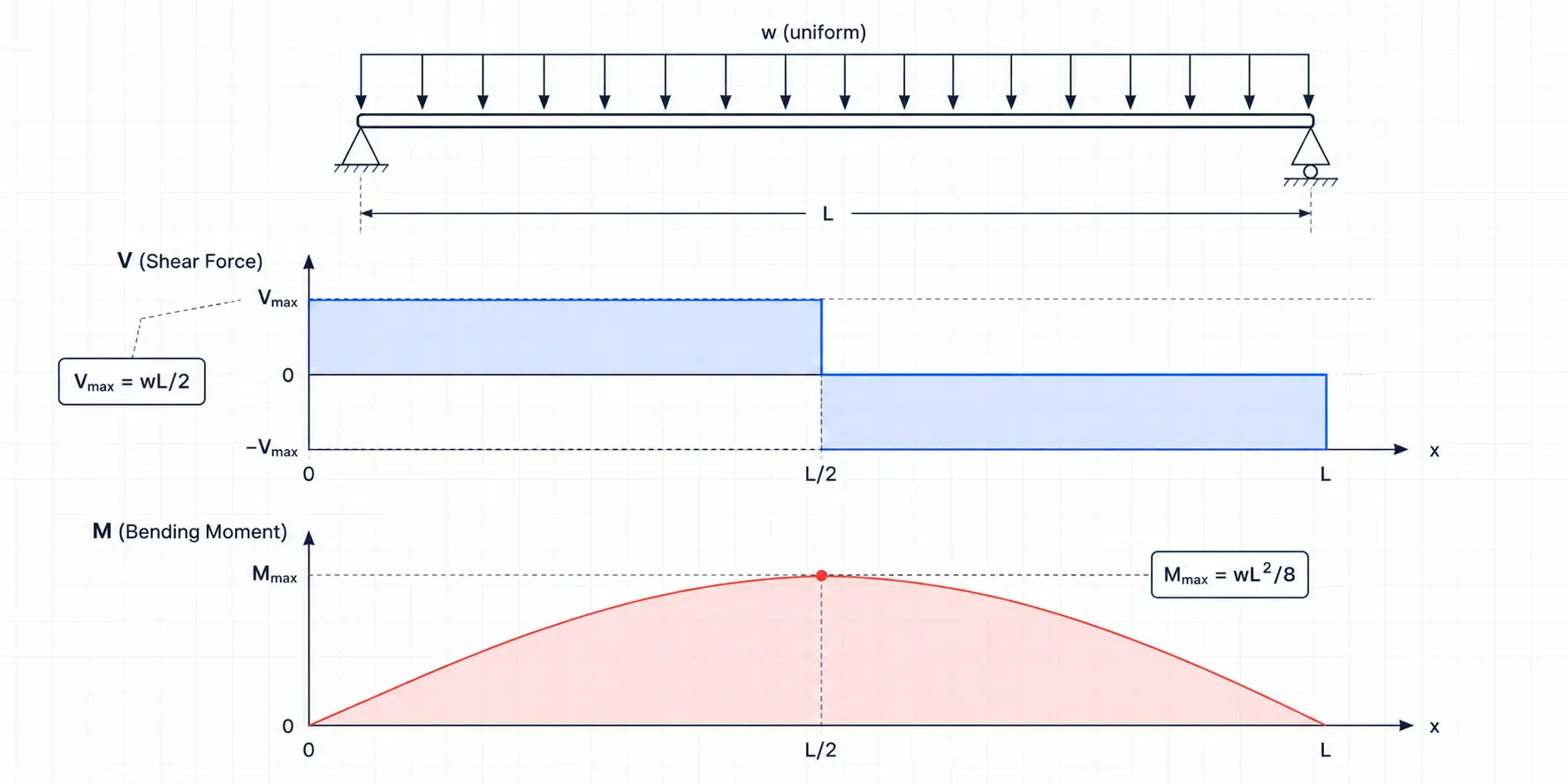
Shear force and bending moment diagrams for a 20-ft simply supported beam with 5 kip/ft UDL. Diagrams generated live in the browser by Solvebility’s structural load calculator.
How Does Tributary Area Affect Column Axial Load?
Tributary area is the floor area that “loads” a given column — it depends on bay dimensions and column position. An interior column carries full bay area (X × Y); an edge column carries half; a corner column carries a quarter. Multiplied by floor loads and number of stories, this gives the total dead and live load the column must resist, then factored by 1.2D + 1.6L per ASCE 7-22 LRFD Combo 2.
Getting tributary area wrong is one of the most common errors on preliminary column design — especially when mixing interior, edge, and corner columns in the same grid.
Interior vs. Edge vs. Corner Columns
For a 25 ft × 25 ft bay:
- Interior column: At = 625 ft²
- Edge column: At = 312.5 ft²
- Corner column: At = 156.25 ft²
Stack 4 floors at 80 psf dead and 50 psf live — factored with 1.2D + 1.6L — and the interior column carries 444 kips while the corner column carries only 111 kips. That’s a 4x difference. Sizing them from the same table is a mistake that shows up in foundation cost.
ASCE 7-22 allows live load reduction for large tributary areas per §4.7. For an interior column with 10+ stories, you can often reduce live load to 40–50% of the code minimum. The calculator includes a simplified reduction toggle — but verify against §4.7.3 for your occupancy category before applying it in a stamped calculation.
Wind Load Calculation Per ASCE 7-22 Chapter 27
Wind load per ASCE 7-22 is calculated by first finding the velocity pressure qz at building height h using qz = 0.00256 × Kz × Kd × V², then applying pressure coefficients (Cp) for windward, leeward, and roof surfaces to get design pressures. Base shear from wind equals net horizontal pressure × exposed wall area. Exposure category (B, C, or D) changes Kz significantly — often by 20% or more.
The Directional Procedure (Chapter 27) is what most US engineers use for regular-shaped buildings. It’s more involved than the simplified method, but it’s the approach you’ll need for permit submittals in most jurisdictions.
Velocity Pressure: qz at Height h
The formula qz = 0.00256 × Kz × Kd × V² converts basic wind speed (mph) to pressure (psf). The Kz factor adjusts for height and exposure:
- Exposure B (urban/suburban): α = 7.0, zg = 1,200 ft — lowest wind speeds at low heights
- Exposure C (open terrain): α = 9.5, zg = 900 ft — standard for most suburban sites
- Exposure D (coastal/flat): α = 11.5, zg = 700 ft — highest pressures; coastal structures
Windward, Leeward, and Roof Pressure Coefficients
| Surface | Cp | Applied To | Note |
|---|---|---|---|
| Windward wall | +0.8 | qz at each height z | Positive = inward pressure |
| Leeward wall | −0.5 (L/B ≤ 1) | qh at roof height | Negative = outward suction |
| Leeward wall | −0.3 (L/B ≥ 4) | qh at roof height | Deeper buildings reduce leeward |
| Flat roof (≤5°) | −0.7 | qh | Suction controls uplift design |
| Gable roof (≤30°) | −0.7 to −0.18 | qh | Varies with pitch and wind direction |
The net horizontal pressure (windward + leeward) drives base shear. At 115 mph / Exposure C / 40 ft height, expect net horizontal pressure around 30–35 psf — enough to control the design of lateral systems in taller or lighter structures.
Seismic Base Shear: How Does ASCE 7-22 §12.8 Work?
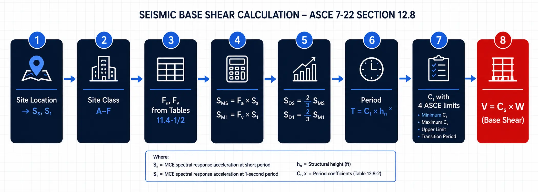
Seismic base shear V = Cs × W, where W is the seismic weight (dead load + applicable portions of live and snow) and Cs is the seismic response coefficient. Cs depends on spectral acceleration (SDS), response modification factor (R), importance factor (Ie), and fundamental period T. ASCE 7-22 §12.8.1.1 applies four limits on Cs to prevent under- and over-design.
The Equivalent Lateral Force (ELF) procedure — §12.8 — is the method every US structural engineer learns first. It’s approximate, but it’s the standard for most regular low-to-mid-rise buildings.
Step-by-Step: From Site Parameters to Base Shear
- Get Ss and S1 from ASCE 7-22 hazard maps or the ASCE Hazard Tool for your site coordinates
- Determine site class (A through F) from geotechnical report or site characterization
- Compute Fa and Fv from ASCE 7-22 Tables 11.4-1 and 11.4-2 based on site class and Ss/S1
- Calculate SMS = Fa × Ss and SM1 = Fv × S1
- Get design accelerations: SDS = (2/3) × SMS and SD1 = (2/3) × SM1
- Estimate period T using T = Ct × hnx (approximate method) — for steel moment frames, Ct = 0.028, x = 0.8
- Compute Cs and apply all 4 limits from §12.8.1.1
- Base shear V = Cs × W
| Structural System | R | Ω₀ (Overstrength) | Cd (Deflection) |
|---|---|---|---|
| Special Steel Moment Frame | 8 | 3 | 5.5 |
| Ordinary Steel Moment Frame | 3.5 | 3 | 3 |
| Special RC Shear Wall | 6 | 2.5 | 5 |
| Ordinary RC Shear Wall | 4 | 2.5 | 4 |
| Special Steel Concentrically Braced Frame | 6 | 2 | 5 |
| Light-Frame Wood Shear Wall | 6.5 | 3 | 4 |
Higher R values mean the system is expected to absorb more energy through ductile behavior — so you can design for lower seismic forces. But higher R requires more detailing, more inspection, and more cost. The right R isn’t always the highest one available.
LRFD vs. ASD: Which Method Should You Use?
LRFD (Load and Resistance Factor Design) and ASD (Allowable Stress Design) both produce safe designs when applied correctly. LRFD typically results in lighter members for gravity-dominated structures because it applies different load factors to different load types. ASD is simpler conceptually and still used for wood and some masonry. Most US structural steel and concrete design now defaults to LRFD per AISC 360 and ACI 318.
| Factor | LRFD (Strength Design) | ASD (Allowable Stress) |
|---|---|---|
| Load factors | Variable (1.2D, 1.6L, 1.0W, etc.) | Unity or slight reduction (0.6–1.0) |
| Resistance factor | φ applied to nominal capacity | Safety factor Ω divides capacity |
| Governing standard | AISC 360, ACI 318, ASCE 7-22 | AISC 360 (ASD chapter), NDS for wood |
| Member efficiency | Typically lighter members | More conservative; slightly heavier |
| Best for | Steel, concrete, multi-load scenarios | Wood, masonry, simple gravity cases |
| LRFD/ASD demand ratio | Typically 1.4–1.6 for gravity; varies with lateral loads | |
When wind or seismic controls, the LRFD/ASD ratio can drop below 1.4 — sometimes to 1.2 or lower. That’s when LRFD gives you the most optimization. For gravity-only warehouse or parking structure design, ASD often gives you essentially the same member sizes with simpler math.
How to Use Solvebility’s Structural Load Calculator
Open the calculator, navigate to any of the 6 module tabs, enter your project values, and results update in real time — no submit button needed. The tool runs in your browser on desktop or mobile with no account, no download, and no spreadsheet required. Start with Module 1 (load combinations) and work through modules based on what your project needs.
Step 1 — Module 1: Load Combinations
Enter service loads in psf: dead (D), live (L), roof live (Lr), snow (S), rain (R), wind (W), seismic (E). The tool evaluates all 7 LRFD and 9 ASD combinations and highlights the governing case. Check the LRFD/ASD ratio to confirm it’s in the expected 1.4–1.6 range.
Step 2 — Module 2: Beam Analysis
Select boundary condition (simply supported, cantilever, or fixed-fixed), load type (point, UDL, triangular), and enter span, load magnitude, E, and I. You get Mmax, Vmax, Δmax, reactions, and SVG diagrams of the shear and moment envelopes. Check the L/360 and L/240 deflection badges.
Step 3 — Module 3: Tributary Area
Input bay dimensions, number of floors, dead and live loads per floor, and column position (interior/edge/corner). The tool calculates tributary area, total D and L, unfactored total, and factored Pu with a plan-view SVG showing the tributary zone.
Step 4 — Module 4: Wind Load
Enter basic wind speed (mph), exposure category, building height, width, length, roof type, and enclosure. The calculator computes Kz, qz, design pressures on windward, leeward, and roof surfaces, and total base shear from wind. This is the ASCE 7-22 Chapter 27 Directional Procedure.
Step 5 — Module 5: Seismic
Input Ss, S1, site class, R, Ie, seismic weight W, and building height hn. The calculator auto-estimates period T using the approximate formula, applies all 4 Cs limits from §12.8.1.1, and shows the governing seismic response coefficient and base shear V. A step-by-step calculation chain is expandable for checking and reporting.
Step 6 — Module 6: Print Report
Enter project name and engineer name, click “Generate / Refresh Report,” and click “Print Report” to get a PDF via the browser print dialog. The report includes all module inputs and governing results with a disclaimer for professional use.
Frequently Asked Questions
A structural load calculator is a digital tool that computes factored design demands — from dead, live, wind, and seismic loads — per code-required combinations like ASCE 7-22. Civil and structural engineers, EITs, contractors, and building inspectors use it for preliminary design, permit calculations, field checks, and client proposals. Any professional who needs ASCE 7-22 load combinations without opening a spreadsheet benefits from it.
The calculator takes service-level loads (D, L, Lr, S, R, W, E) entered in psf and applies all 7 LRFD strength combinations from ASCE 7-22 §2.3.1 and all 9 ASD combinations from §2.4.1 simultaneously. It evaluates max(Lr, S, R) where applicable, identifies the governing combination (highest factored demand), and displays it in red with its magnitude in psf. Results update with every keystroke — no form submission needed.
The calculator is accurate for preliminary design and calculation verification, and the built-in report module generates a print-ready summary. However, all calculations must be reviewed and stamped by a licensed professional engineer before use in permitted construction. The tool’s disclaimer states this explicitly: it’s a computational aid, not a substitute for licensed structural engineering judgment.
Use LRFD for steel and concrete structures where AISC 360 or ACI 318 apply — it generally produces lighter, more economical designs, especially when multiple load types act simultaneously. Use ASD for wood (NDS), masonry, and cases where client or firm standards require it. Both methods are code-compliant; the governing combination and resulting demand will differ, which is why the calculator shows both simultaneously with their ratio.
It’s completely free. No account, no subscription, no download. All 6 modules — load combinations, beam analysis, tributary area, wind load, seismic analysis, and report generation — run in your browser at no cost. Solvebility doesn’t require sign-up or payment for any of its civil engineering calculators.
ETABS and SAP2000 are full finite element analysis platforms for complex, 3D structural systems — they cost thousands of dollars per seat and require significant training. A structural load calculator like Solvebility’s handles the code-required preliminary analysis: factored loads, simple beam design, tributary areas, and lateral forces. It’s the right tool for the 80% of calculations that don’t need FEA — and it takes seconds instead of hours to set up.
Yes — the seismic module uses ASCE 7-22 §12.8 ELF procedure, which applies nationally. You enter your site-specific Ss and S1 values (from the ASCE Hazard Tool or USGS seismic maps), site class, and structural system parameters. The tool then handles all Cs calculations and limits. For Site Class F (liquefiable soils) or irregular structures, site-specific analysis is required and this tool’s results are a starting estimate only.
The most common mistake is checking only LC2 (1.2D + 1.6L) and ignoring LC5 (0.9D + 1.0W) for uplift and overturning. LC5 uses a reduced dead load factor of 0.9, which can produce net tension in leeward columns under high wind — something that doesn’t show up if you only check gravity combos. Always evaluate all combinations, especially when wind or seismic is significant.
Run Your Structural Load Checks in the Browser — Free
A proper structural load calculator does more than arithmetic. It applies ASCE 7-22 load combinations correctly, checks beam serviceability limits, accumulates column loads from tributary areas, and runs wind and seismic procedures — all in one place, all in real time.
Solvebility’s free tool covers all 6 modules without a paywall, a login, or a spreadsheet. Whether you’re on a job site checking a floor beam or at your desk running preliminary seismic base shear for a permit submittal, it’s built to work on any device in under a minute.
Open the calculator, enter your values, and you’ll have ASCE 7-22 compliant results before your next cup of coffee is done.
References & Standards
- ASCE/SEI 7-22 — Minimum Design Loads and Associated Criteria for Buildings and Other Structures. American Society of Civil Engineers, 2022. asce.org
- ACI 318-19 — Building Code Requirements for Structural Concrete. American Concrete Institute, 2019.
- AISC 360-22 — Specification for Structural Steel Buildings. American Institute of Steel Construction, 2022.
- IBC 2021 — International Building Code. International Code Council, 2021.
- ASCE Hazard Tool — Design Parameters for ASCE Standards. ascehazardtool.org
- AISC Design Guide 3: Serviceability Design Considerations for Steel Buildings. 3rd ed., 2003.